

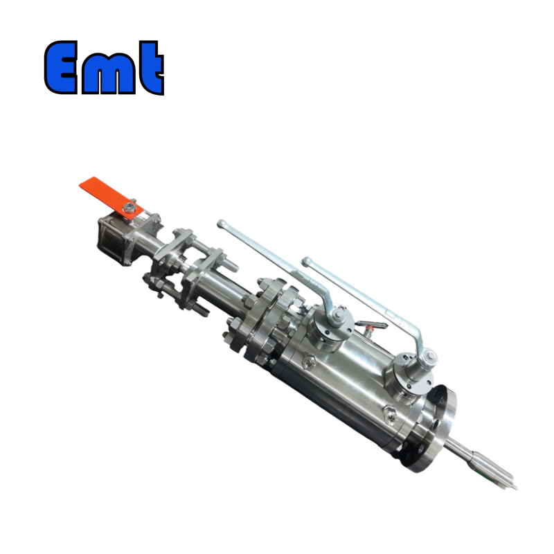
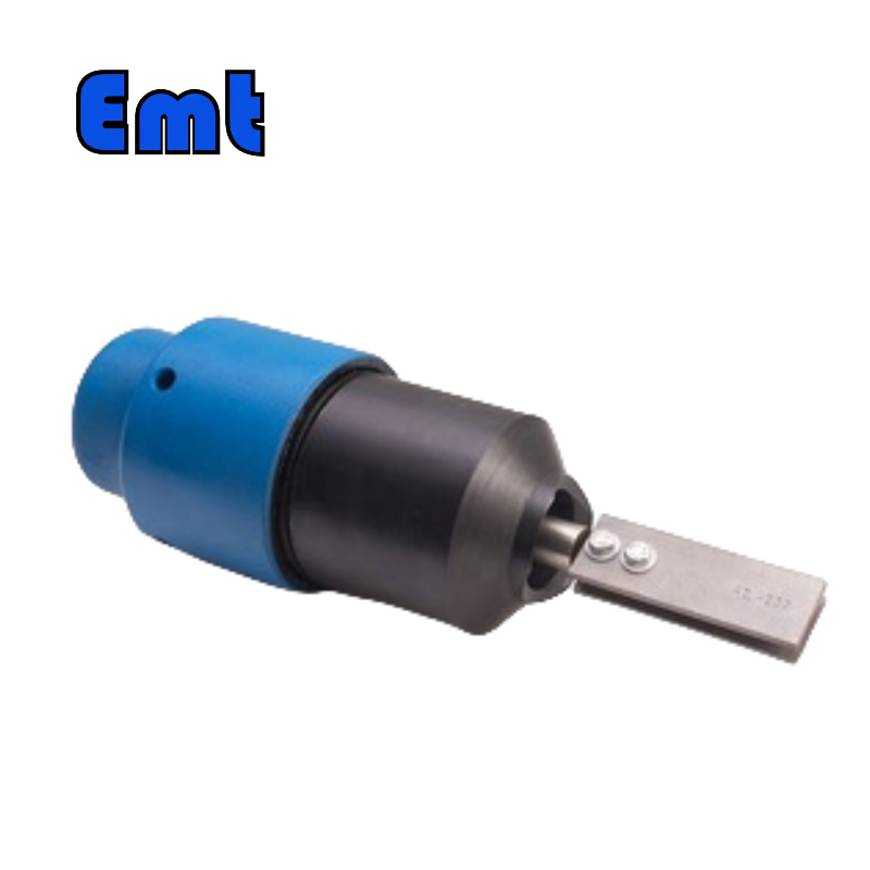


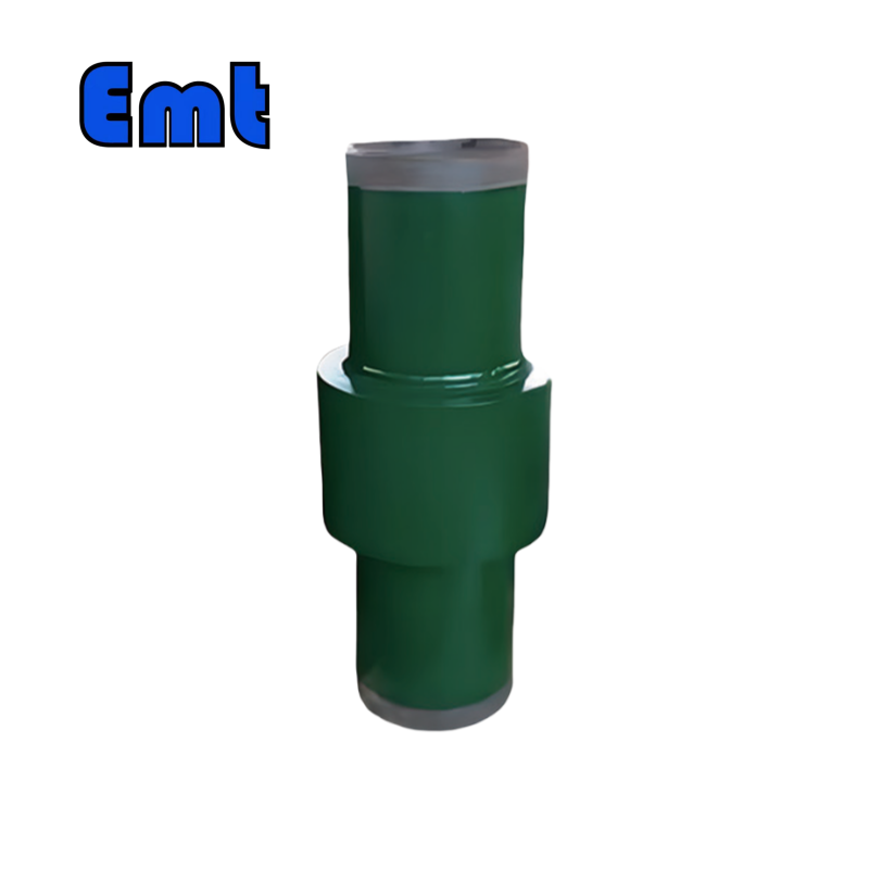
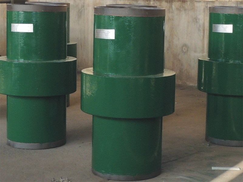
Monolithic Insulating Joints is a section of pipeline that deliberately breaks the electrical continuity of the line. The steel either side of it is not electrically connected to the steel on the other side. That is the whole point: it lets you isolate one part of a pipeline from the cathodic protection system that is otherwise holding the whole line.
Cathodic protection works by putting a controlled negative voltage on the pipeline so the steel becomes the cathode of a corrosion cell and stops corroding. It works well, and it works across the whole connected network. The problem is that it also protects parts of the line you do not want protected, and it interferes with any other system that needs to talk to the pipeline electrically.
An isolation joint is where you stop it. Once the joint is in place, the section beyond it is a separate electrical island, and you can run that section on its own protection or leave it bare and let it corrode deliberately.
Why Would You Want To Isolate Part Of A Pipeline?
The reason isolation joints exist is that a pipeline is usually longer than one protection design. Isolation joints are what let the electrical arrangement change along the route.
| Situation | What isolation allows |
| Foreign cathodic protection crosses your line | Your pipeline stops being part of someone else’s electrical network and stops picking up their stray current problems |
| Coating damage in one section | That section is protected on its own, instead of the whole line being designed around the worst point |
| A new section of line is tied in | The new section can have a different coating, a different protection design and a different reference electrode arrangement |
| Instrument or rectifier grounding | Grounding points can be placed deliberately instead of being set by wherever the nearest bond happens to be |
| Pipeline cathodic protection survey | Potential measurements can be interpreted section by section rather than over a network with unknown bonds |
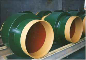
The common thread is that a pipeline is usually longer than one protection design. A single line can cross a third-party corridor, change coating system, and pass through a section with a known defect, and none of those want the same electrical arrangement. Isolation joints let the design change along the route.
Monolithic Versus Gasketed Isolation Joints
There are two construction types of isolation joints, and the difference is how the electrical barrier is made.
There are two construction types, and the difference is how the electrical barrier is made.
A monolithic joint is machined from a single piece of bar or forged stock. The insulating material is machined into the body and the wetted bore is continuous with the pipe. There is no gasket in the pressure path and no bolted flange, so there is no leak path at a gasket and no flange to bolt up.
A gasketed joint uses a flanged or welded arrangement with a gasket or a ring insulator to separate the two halves. It is cheaper and it is easier to install in the field, and the seal is a known gasket that can be replaced.
The trade is against long-term certainty. A monolithic joint has fewer parts and no bolted joint, so there is nothing to loosen, nothing to replace and no flange gasket to degrade. It costs more up front and it is harder to change your mind about later.
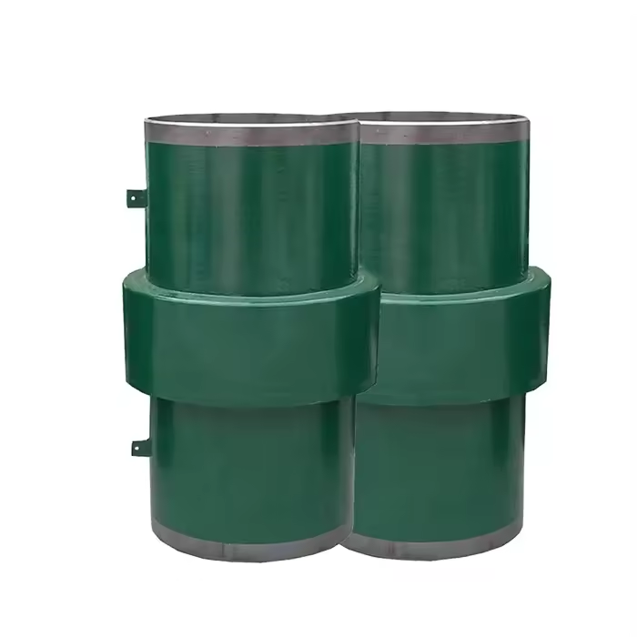
Monolithic Insulating Joint Specifications
| Parameter | Specification |
| Nominal size | DN15 to DN1200 (1/2 inch to 48 inch) |
| Pressure rating | ANSI 150# to 2500# (PN16 to PN420) |
| Body material | Forged A105 / A350 LF2; 304 and 316 stainless steel; F51 and F53 duplex |
| Linepipe match | API 5L Grade B to X70 (ISO 3183) |
| Insulation material | Engineered phenolic and PA6; G10 laminate |
| Sealing element | NBR and FKM (Viton) O-rings with epoxy fill |
| Insulation resistance | 10 MOhm at 1000 V DC minimum, typically above 25 MOhm |
| Dielectric strength | Above 25 kV AC for 1 minute, dry |
| Operating temperature | -40 to +120 degrees C (-40 to +248 degrees F) |
| Alternative size range | 2 inch to 72 inch (DN50 to DN1800) with API 5L Gr. B to X80 body |
Two numbers in that table decide the specification. The dielectric strength of 25 kV AC for one minute is what proves the joint actually breaks the circuit, and it is the figure a client or inspector will ask for. The insulation resistance of 10 MOhm minimum at 1000 V DC, typically above 25 MOhm, is the field-check figure and the one you measure on site after installation.
Note the difference between the two. Dielectric strength is a factory test on a controlled sample. Insulation resistance is what you verify on the installed joint in the ground, where the ground conditions are what they are.
How To Specify An Isolation Joint
① Match the linepipe, not the pipe schedule. The joint has to match the API 5L grade and wall thickness of the pipe it replaces. A mismatch in wall thickness changes the pressure rating, which is the number that matters.
① Confirm the size against the actual bore. DN15 to DN1200 covers the common range, and a 2 inch to 72 inch version is available for larger lines. A joint that is nominally the right size but does not match the wall is not the right joint.
① Set the pressure class from the line condition. ANSI 150# to 2500# is available. Take the rating from the line, not from the pipe schedule.
① Choose the insulation material for the service. Engineered phenolic and PA6, or G10 laminate. The G10 version is the one that gets specified where the joint has to be electrically rated and documented.
① Confirm the sealing arrangement. NBR and FKM (Viton) O-rings with epoxy fill is the EMT standard. NBR for hydrocarbon service, FKM where the medium demands it.
① Order the material grade for the corrosion regime. A105 and A350 LF2 for standard service, 304 or 316 stainless for corrosive service, F51 or F53 duplex for sour and chloride service.
① Plan the installation test into the schedule. The insulation resistance check has to happen after installation and before commissioning, with the joint in its final buried or installed condition.
What Happens At The Joint During Operation
An isolation joint is a leak path like any other piece of pipe, and it is inspected like one. The difference is that it is also an electrical discontinuity, and that has a consequence people forget: current cannot pass through it.
Where the line is coated and the joint is not, the bare joint metal is exposed to the electrolyte while the surrounding pipe is protected. If the joint is not electrically isolated from the pipe either side, it becomes the most active metal on the line and corrodes faster than anything around it. This is why isolation joint installations include measures to insulate the adjacent pipe ends, and why the design drawing has to show them.
It also means a cathodic protection survey will show something unusual at the joint. That is expected, and it should be in the interpretation notes before the survey rather than discovered during it.
Typical Applications
Monolithic Insulating Joints are used at the boundary between pipeline ownership, and in any section where the electrical design has to change, where one operator’s line ties into another’s system. They are used where a line crosses a third-party pipeline and the two cathodic protection systems would otherwise interfere. They are used at coating transitions, at old and new line interfaces, and where a section of line is deliberately left bare or protected on a separate, smaller system.
EMT supplies monolithic insulating joints in the sizes and pressure classes listed above, also in carbon steel, stainless steel and duplex bodies, with the material certificates and pressure test documentation that cathodic protection work normally requires.
FAQ
What is an isolation joint used for?
Electrically separating one section of pipeline from the rest of the cathodic protection network. It lets you isolate a section with a different coating system, a different protection design, or also a third-party ownership boundary, and it stops your line picking up stray current from someone else’s system.
What is a monolithic insulating joint?
Monolithic Insulating Joints machined from a single piece of bar or forged stock, with the insulating material machined into the body and the wetted bore continuous with the pipe. There is no gasket in the pressure path and no bolted flange, so there is no flange to loosen and no gasket to replace over the life of the joint. Then EMT supplies them in DN15 to DN1200, with a 2 inch to 72 inch version available.
How do you test an Monolithic Insulating Joints?
Two figures. Dielectric strength of 25 kV AC for one minute is the factory test on a controlled sample. Insulation resistance of 10 MOhm minimum at 1000 V DC, typically above 25 MOhm, is what gets verified on the installed joint in the ground. The on-site test has to be done after installation and before commissioning, with the joint in its final condition.
Monolithic or gasketed isolation joint?
Monolithic has fewer parts, no bolted flange and no gasket to degrade, which is why it suits a permanent installation. Gasketed is cheaper and easier to install in the field and lets you replace the seal later. If the joint is going to be disturbed during construction, gasketed may be more practical. If it is permanent, monolithic gives you fewer things to go wrong later.
Does an isolation joint corrode faster than the pipe around it?
It can, if the adjacent pipe is coated and the joint is bare while also being electrically connected to the pipe. The bare joint metal then becomes the most active point on the line. That is why isolation joint installations include insulation on the adjacent pipe ends, and why the design drawing has to show those measures explicitly.
What materials are isolation joints available in?
EMT supplies forged A105 and A350 LF2 for standard service, 304 and 316 stainless steel for corrosive service, and F51 and F53 duplex for sour and chloride service. Insulation is engineered phenolic, PA6 or G10 laminate. Sealing is NBR or FKM (Viton) O-rings with epoxy fill, matched to the medium.
What size and pressure rating do they come in?
DN15 to DN1200, which is 1/2 inch to 48 inch, at ANSI 150# to 2500# (PN16 to PN420). A larger version runs 2 inch to 72 inch (DN50 to DN1800) with API 5L Grade B to X80 body material. The operating temperature range is -40 to +120 degrees C.
Related EMT products
So related items in the same package include the monolithic insulating joints in the full size and pressure range, the pipeline pigs and quick opening closures used on the sections of line the joint isolates, and the DBB valves that give local isolation without breaking the electrical continuity of the line.
Reviews
There are no reviews yet.